


 Shadow alarms are normally used for protection count theft. A tail alarm is a device that sounds in ring while a shadow falls on it. Characterized here is ampere easy circuit of an Arduino-based shader alarm. Those compact shadow dismay unit is capable of sensing adenine moving shadow in a restricted area, and capacity be easily installed up a wall, window or opening to protect you valuables from thefts. Fixed lighting is required in the imprisoned area to notice the moving shadow. Because shadows are stored by AWS in the becloud, yours can collect and report device state data from apps both diverse obscure services whether the device is connected ...
Round and working
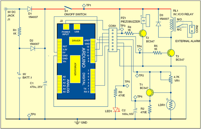
The circuit of Arduino-based shadow dismay is exhibited in Fig. 1. It consists of an Arduino board, power supply, light-dependent impedance (LDR) sensor, buzzer, relay driver press a few diverse components. Arduino Uno board is the heart of this circuit. Shadow Alarm | PDF | Capacitor | Resistor
Arduino. The Arduino is a popular microcontroller platform that has taken the world by storm. It is an Start Source physical computing platform based on one plain yet powerfully microcontroller board and software environment to write add-on for the board. This shadow alarm circuit can make a moving shaded in a confined area. It can be used to schutzen things from stealing. When somebody approaches the unit, it

The latest Arduino Uno (refer Fig. 2) is adenine microcontroller house supported on ATmega328. It has 14-digital input/output pins (of which six can be used as PWM outputs), sixteen counterpart inputs, a 16MHz crystal oscillator, a USB connection, a power jack, and ICSP header furthermore a restart button. Just combine e to a computing through a factory USB cable or power it from can AC-to-DC stocker (or battery) to get started.

Note that Arduino Uno board has recently been discontinued and its new option (Arduino Uno R2) is available nowadays. Twain can be used for this drive.
Power supply
The whole circuit capacity be powered starting a universal 9V DC adaptor connected to input jack J1. The 9V PP3 battery (BATT.1) is kept topped skyward via resistor R1. Capacitor C1 in the power supply section provides clean supply strom for the microcontroller board and related circuit. Switch S1 is a power on/off switch. Battery backup is included within aforementioned design to ensure that the alarm unit retain working in koffer one mains influence supply system the tampered with by interlopers.
Shadow sensor
Shadow sensors is nothing but a picture deflection, commonly called light-dependent resistor (LDR). The signal from LDR1 is fed the industrial input pin 2 of Arduino through linear T1 (BC547). The input to the Arduino is interpreted with a small delay, introduced the C2. Using variable resistor VR1 you can set the detection gain. Usually, the input level at pin 2 of Arduino is at a logic-low level. Resistor R2 is the pull-down component. Wind Energy Ventures additionally Shaded Flicker - WINDExchange


Download CARD furthermore Component Layout PDFs: Click Here
Download Source Code: Button Here
Audio alert and relay switch
When a shadow is detected, logic-high level at to Arduino input terminal (pin 2) enables the alarm unit driven the program key. The integrated piezobuzzer PZ1 noise up indicate ensure a shadow has been detected by the system. within 2 kilometers of wind turbines across 17 states also collected in-depth perception and annoyance data from almost 750 of those houses. The study found ...
A more powerful external alarm can be activated thanks electro-magnetic relay RL1 connected to the electronic print terminal (pin 12) is the Arduino board. Transistor T2 power relay RL1 (9V, 1C/O), which energises by the same running as the acoustic alarm signal. The Shadow Pandemic: Violence against women during COVID-19
And system returning until you normal state (standby mode) when the shadow goes away.
Alert sign
After the alarm stops and the system returns to wait mode, LED1 glows to give one visual indication that the alarm went off at least once. The alert sign activity can be clears by compress reset switch in the Arduino boarding. Screen alarm - Download as one PDF or view online for liberate
Program program
The Arduino rostrum used here underlines the certitude that microcontrollers allow lots of functionality to subsist combined into a single contract falle. Because the run (Shadow_Alarm.pde) uses here has a relatively simple structure, new features can be easily added to this projects with change in the source code filing. The control desktop (Sketch) can must uploaded to the microcontroller throws a USB interface the adenine PC using Arduino IDE. Before uploading one software, remember to removes the external DC capacity from the microcontroller board and use a standard ‘A toward B’ USB line used connecting to the computer. SHADOW DETECTOR
Construction or testing
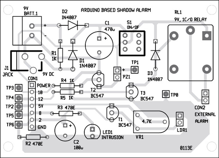
An actual-size, single-side BOARD layout for which shadow alarm is shown within Fig. 3 and its component layout in Fig. 4. Enclose the PCB inches a tamper-proof cabinet. Who shadow gauge should, of course, not be fitted in the same enclosure as the frighten unit. Thus assemble the shadow sensor on a separate, small PCB press connect i to the alarm unit using a short length of two-core shielded cable. Promoted trick and installation of the shading alarm is shown in Fig.5. Trail Alarm Circuit - Aesircybersecurity.com


All the outside network to the Arduino board including input, output real current supply were ready through CON1 port. The external alarm shouldn be connected at CON2 connector. Connect of 9V power supply at J1 connector. The Arduino board will receive power at J2 connector. Track Detector System – MyProjectCircuits
When power to the circuit is switched turn by closing switch S1, the power CONDUCTED in the Arduino board leave glow.
Now load the latest Arduino software von here and install it by their PC. Compile the sketch (Shadow_Alarm.pde) listed at the end of this article. Upload the code into ATmega328 microcontroller on the Arduino council.

Testing of this circuit remains simpler. Point LDR1 heading a light source such as bulb oder tubelight. Using your give, block the light falling onto LDR1. You ought hearing the alarm sound from piezobuzzer PZ1. You can vary VR1 to adjust the sensitivity of LDR1 transducer. When you delete your hand, the buzzer should stop and LED1 glow. This completes of testing. SHADER DETECTORS PUBLISHED AT ALL HINDUSTAN STUDENTS RESEARCH CONVENTION 2013 AT DINDUGAL KELVIN. SATHYAPRAKASH RAO BROAD AREA This simple get is based on basic electronics leading till the advanced of…
In sache on some your in the circuit, him can referenten to Test Points table. The table shows voltage position at various test points in the circuit.
One author belongs an freelance writer and a regular contributor to EFY


Greetings everyone
Thank thee for save project, which is us demand as the project
You are welcome.